AV MOUNTING & STRUCTURES MALAYSIA

Choose the right support before choosing the bracket.

A safe AV installation starts with the equipment, load path, building surface, movement and maintenance access—not the mount model alone.

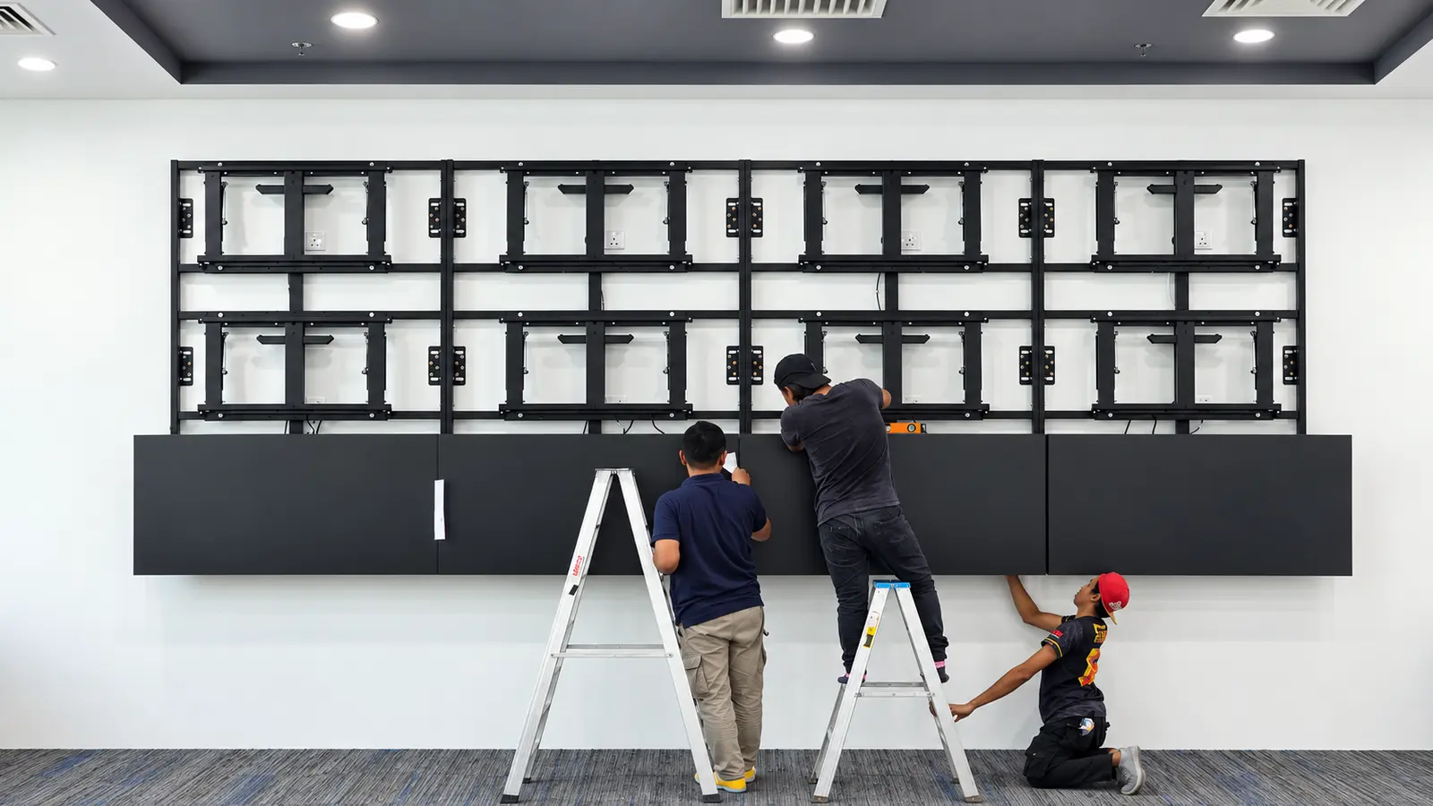
PNSS technicians installing commercial displays on a purpose-built video wall mounting structure
Verify the load pathEquipment weight is only one part of the structural requirement.
Plan movement and accessAllow for alignment, cables, ventilation and future servicing.
Confirm the actual siteFinal fixing and fabrication depend on measured building conditions.

START WITH THE INSTALLATION

Four questions narrow the right support system.

The same display or projector may need a very different structure when the surface, movement, viewing position or maintenance route changes.

  1. 01What must be supported?

    Confirm the exact model, quantity, dimensions, weight, VESA or mounting points and accessories.

  2. 02Where will it be fixed?

    Identify the wall, ceiling, floor or independent frame and verify the supporting material behind the finish.

  3. 03Must it move or retract?

    Define tilt, swivel, height change, front service, lift travel and safe operating limits.

  4. 04How will it be maintained?

    Reserve safe access for alignment, ventilation, cables, replacement and inspection.

SIX COMMON SUPPORT SYSTEMS

Match the mounting type to the real application.

Use these categories to identify the likely direction. PNSS confirms the final mounting, fasteners, restraints and responsibility boundary after technical review.

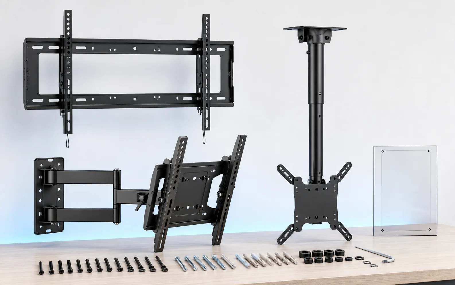
Wall, articulating and ceiling pole display mounting bracket options

01 · DISPLAYS

Wall and ceiling display mounts

Suitable for a single commercial display when the position and supporting surface are known. Fixed and tilt mounts keep the installation compact; articulating or ceiling-pole arrangements add movement or solve room-layout constraints.

Best fit
Meeting rooms, classrooms, lobbies and public information displays.
Confirm first
VESA, total weight, centre of gravity, wall or ceiling construction and viewing height.
Service planning
Allow access to power, signal cables, locks and display replacement.
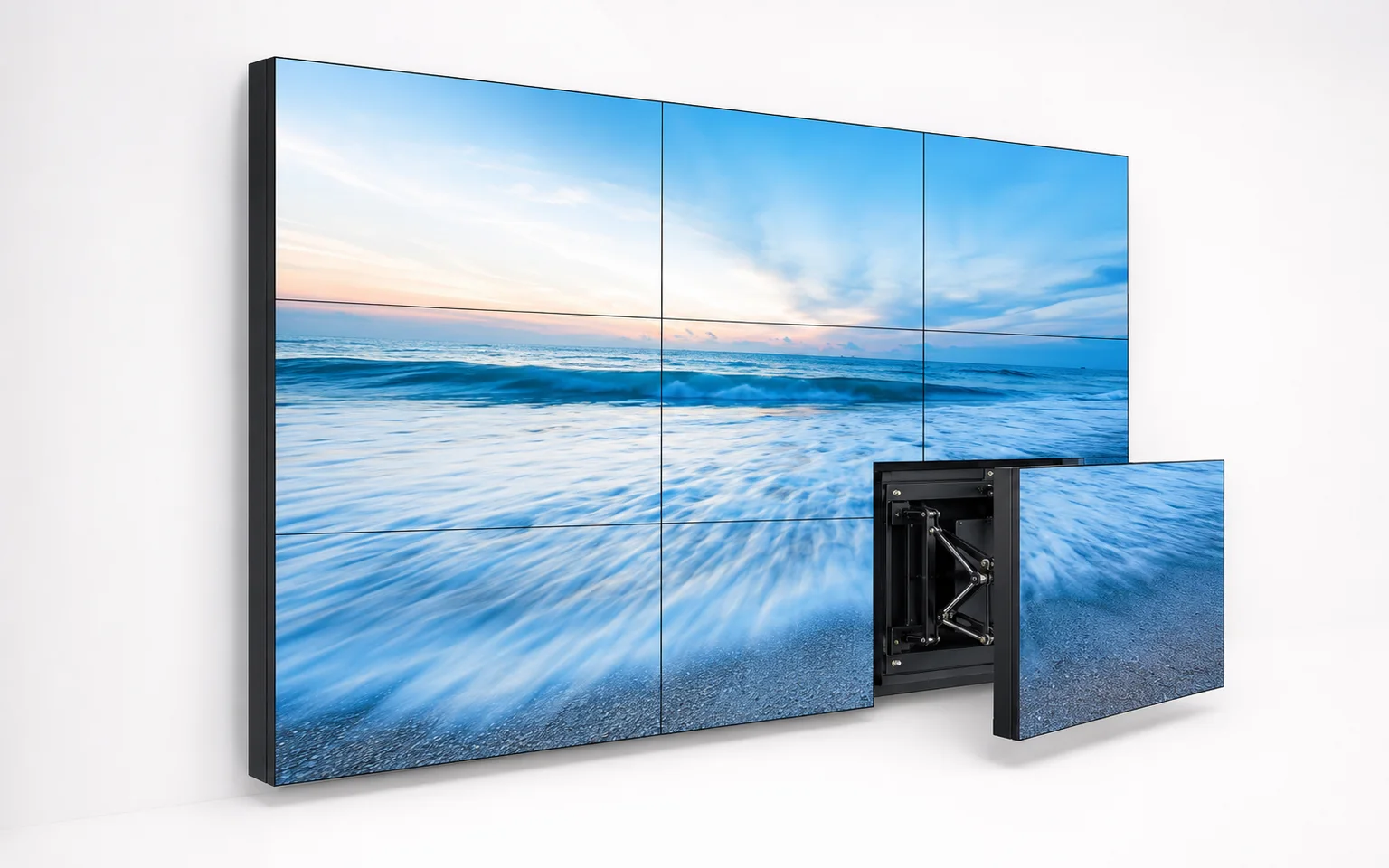
Front-service video wall bracket with one display pulled forward for maintenance

02 · MULTI-DISPLAY

Video wall brackets

Designed for accurate tiled-display alignment and repeatable panel positioning. A front-service pop-out mechanism can reduce the need for a rear access corridor, but travel space and cable movement still require planning.

Best fit
Operational display walls, command centres, lobbies and multi-screen signage.
Confirm first
Wall flatness, combined load, matrix dimensions, bezel gaps and ventilation.
Service planning
Check pop-out travel, panel removal sequence and safe access to every display.
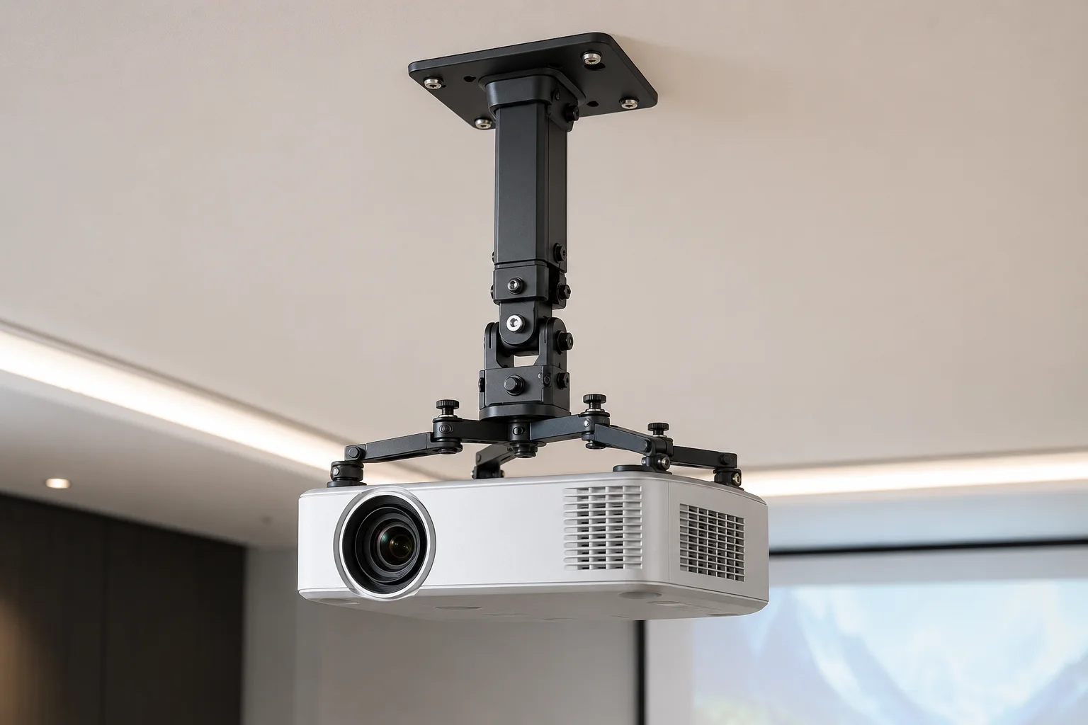
Professional ceiling bracket supporting a projector

03 · PROJECTION

Projector brackets and scissor lifts

Fixed brackets suit permanent positions, while swing arms, height-adjustable mounts and concealed lifts solve specialist geometry or service needs. The support must preserve the lens axis and image alignment.

Best fit
Classrooms, halls, auditoriums, simulation rooms and specialist installations.
Confirm first
Projector weight, lens position, throw, ceiling structure, movement envelope and power.
Service planning
Provide safe lowering or access, secondary restraint, limits and collision clearance.
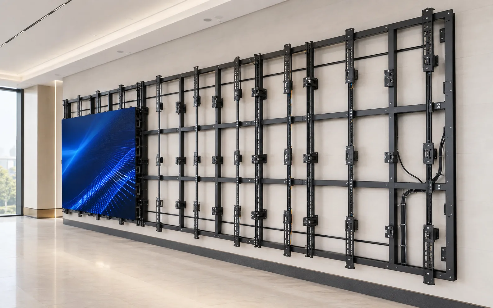
Metal support frame for a direct-view LED wall installation

04 · DIRECT-VIEW LED

LED wall metal frames

An LED wall structure must hold cabinet alignment, flatness and total system load while coordinating power, data and ventilation. Standard wall mounting is not always suitable for large or architectural installations.

Best fit
Auditoriums, stages, command centres, lobbies, showrooms and feature walls.
Confirm first
Cabinet layout, total load, floor or wall datum, tolerances and front or rear service method.
Service planning
Reserve access for modules, power supplies, data components and heat management.
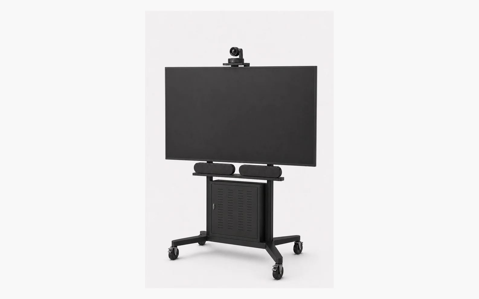
Mobile display and video conference stand with camera, equipment cabinet and lockable wheels

05 · MOBILE

Display and video conference stands

A mobile stand supports flexible room use without permanent wall fixing. Stability depends on the complete system—including the display, camera, speakers, accessories, cables and any equipment stored below.

Best fit
Training rooms, classrooms, multipurpose spaces and temporary events.
Confirm first
Total weight, VESA, height, wheelbase, doorway width, floor condition and cable reach.
Service planning
Use lockable wheels, controlled cable routing and a safe method for moving between rooms.
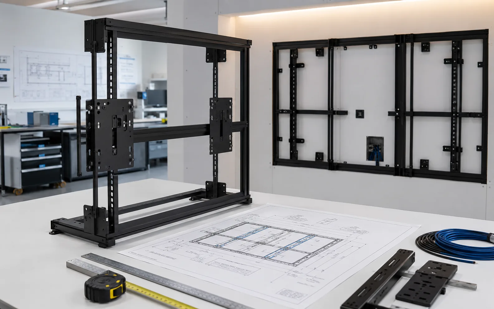
Custom AV mounting structure planning with steel frame and technical drawing

06 · SPECIAL REQUIREMENT

Custom-designed AV structures

A purpose-designed frame, swing arm, lift or stand is considered when standard products cannot safely meet the geometry, movement, access or architectural requirement.

Best fit
Specialist rooms, restricted service spaces, stages and unusual architectural conditions.
Confirm first
Equipment data, measured site dimensions, load path, movement and responsibility boundaries.
Service planning
Develop drawings, material and finish, safety provisions, approvals, testing and commissioning.

QUICK COMPARISON

Which mounting direction usually fits?

This table supports early planning only. Final capacity, fixing and suitability must be confirmed for the actual equipment and site.

Support typeUse whenCritical checkAccess approach
Display mountOne display has a defined wall or ceiling position.VESA, weight and supporting surface.Front, side or articulating access.
Video wall bracketMultiple displays must align as one canvas.Combined load, wall flatness and matrix tolerance.Pop-out front service or planned rear access.
Projector bracket or liftLens position and throw geometry are fixed.Lens axis, ceiling load and movement envelope.Safe lowering, swing-out or service platform.
LED support frameLED cabinets form a large precise surface.Total load, datum, flatness and ventilation.Front module service or rear corridor.
Mobile standThe system must move between spaces.Complete system weight, stability and route.Open component access with controlled cables.
Custom structureStandard products cannot meet the requirement.Documented geometry, loads and approvals.Designed around the agreed maintenance method.

FROM REQUIREMENT TO INSTALLATION

A safer five-step engineering process.

PNSS coordinates the mounting requirement with the AV system and building condition so product selection, fabrication and site work remain connected.

  1. 1SurveyMeasure the position, access route and supporting surface.
  2. 2VerifyConfirm equipment data, loads, movement and cable needs.
  3. 3DesignSelect a standard mount or develop a project-specific structure.
  4. 4CoordinateAlign fixing, power, data, finishes and responsibility boundaries.
  5. 5InstallMount, align, restrain, inspect and hand over the system.

FAQ

Common AV mounting questions.

Can PNSS confirm a mount from the screen size alone?

No. The exact model, total weight, VESA or mounting points, accessories, orientation and site condition are required. Screen size is only an early reference.

Can a large display be fixed to any wall?

No. The visible wall finish does not confirm the supporting structure. The substrate, internal framing, anchor method, load path and installation access must be verified.

When is a custom structure necessary?

A custom structure may be required when standard mounts cannot meet the equipment geometry, movement, maintenance access, architectural finish or safety requirement.

What information should we send for assessment?

Provide the equipment model, quantity, weight, dimensions, VESA or fixing points, proposed location, wall or ceiling construction, movement requirement, service method and available drawings or site photographs.

PLAN THE SUPPORT SYSTEM

Send us the equipment and installation details.

PNSS can review the model, mounting position, building condition, movement and maintenance access before recommending the next step.

Request an assessment

Continue exploring

Related solutions and resources

SOURCE & REVIEW NOTE

Engineering guidance with traceable context.

Prepared by PNSS Tech using project and integration experience together with referenced manufacturer documentation. Product availability, compatibility and project-specific requirements are validated during engineering and quotation.

Reviewed: 21 September 2026 · Malaysia