What exactly is the listening area?
Coverage should follow where users actually need the service, not simply the architectural room boundary.

Technical selection guide · Malaysia
Why metal loss, electromagnetic noise, overspill, room geometry and commissioning determine the induction-loop architecture long before the final Ampetronic driver is selected.
Coverage should follow where users actually need the service, not simply the architectural room boundary.
Rebar, metal decks, raised floors and ceiling grids can weaken the magnetic field and reduce high-frequency clarity.
Magnetic spill can interfere with other loops or extend into spaces where privacy or separation matters.
The loop is only as useful as its source: microphone, PA, conference, TV or DSP routing must be defined correctly.
Commissioning and measurement should be included in the specification so the final field can be verified and documented.
Example loop design diagrams
These simplified plan-view examples show why a counter, a normal room and a low-spill application may require different loop geometry.
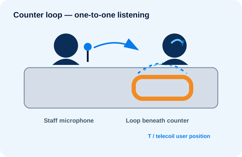
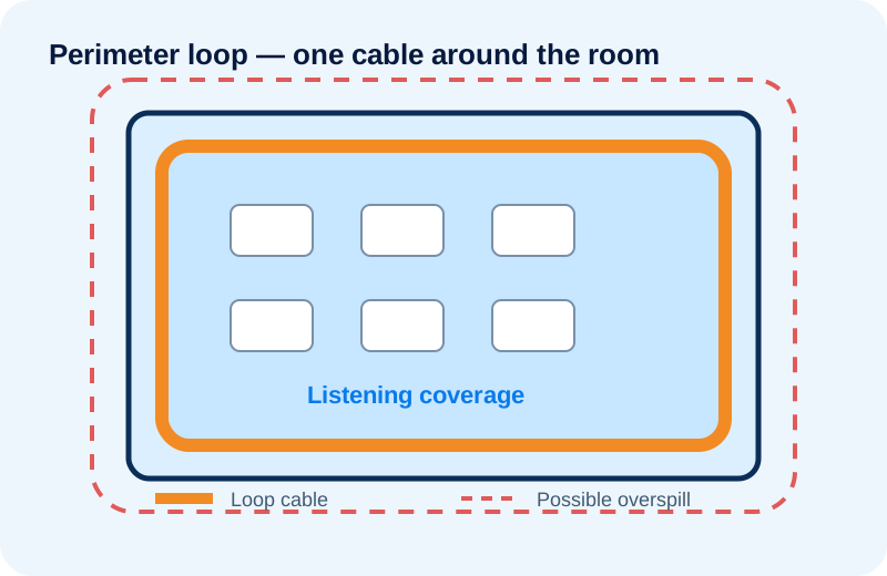
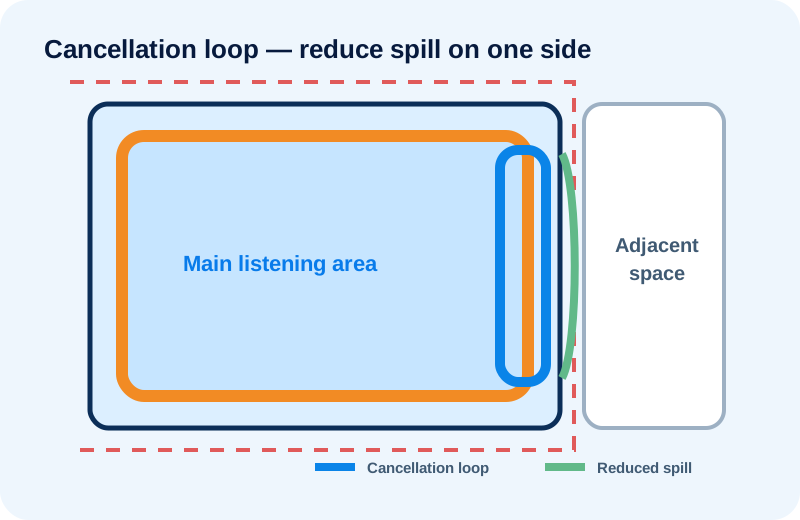
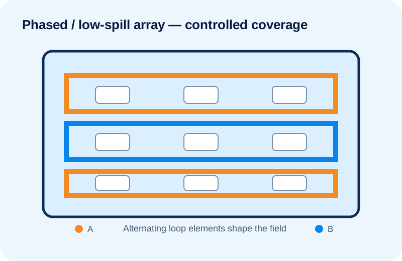
Concept examples only: these diagrams are not installation drawings. Final cable spacing, phasing, driver selection and coverage must be based on the actual floor plan, construction metal, electromagnetic noise, required overspill control and commissioning target.
| Layout | Useful where | Main design concern |
|---|---|---|
| Counter / overspill loop | Defined one-to-one communication position | User position and counter construction |
| Perimeter loop | Suitable room with manageable metal loss | Coverage uniformity and external spill |
| Cancellation loop | Spill needs control on one side | Cancellation geometry |
| Loss-control array | Larger / metal-rich areas | Compensating for building loss |
| Ultra-low-spill / phased array | Adjacent rooms, privacy, multiple nearby systems | Horizontal and vertical spill control |
A room may look simple on the drawing yet behave very differently electromagnetically. Ampetronic recommends assessing background magnetic noise and metal loss before final specification where these factors are likely to affect performance.
Can come from electrical distribution, lighting or wiring faults and may mask the useful loop signal.
Quantifies how much the building structure attenuates the magnetic field and high-frequency response.
Uses the actual listening area and loss conditions to establish a suitable loop topology and driver requirement.
Room aspect ratio, loop layout, required current, metal loss, background magnetic noise, seating pattern and overspill requirements all affect the design. Floor area alone is not enough for reliable equipment selection.
Conductive metal in reinforced concrete, raised floors, ceiling grids and other building structures can weaken and distort the magnetic field, especially at higher frequencies. Site testing and an appropriate loop topology may be required.
Overspill is the magnetic field extending beyond the intended listening area. It can cause interference with nearby loops and may be undesirable for adjacent rooms or confidential spaces.
A perimeter loop can be effective for suitable rooms with manageable metal loss and no strict spill requirement. Low-spill or phased-array designs use multiple loop elements to control coverage, compensate for difficult construction and reduce spill into adjacent areas.
Yes. Compact counter-loop systems can provide localised one-to-one hearing assistance at reception desks, ticket counters, service windows, intercom points and help desks.
Commissioning uses a calibrated field-strength measuring process to verify magnetic background noise, field strength, frequency response and coverage against the project performance target. IEC 60118-4 is the principal international performance standard used for hearing-loop systems.
Send the drawings before the finishes and equipment are locked. Early coordination gives the project more options for conductor routing and spill control.